


PLYODYNE® PRO WALL
The complete movement system
Wall-mounted
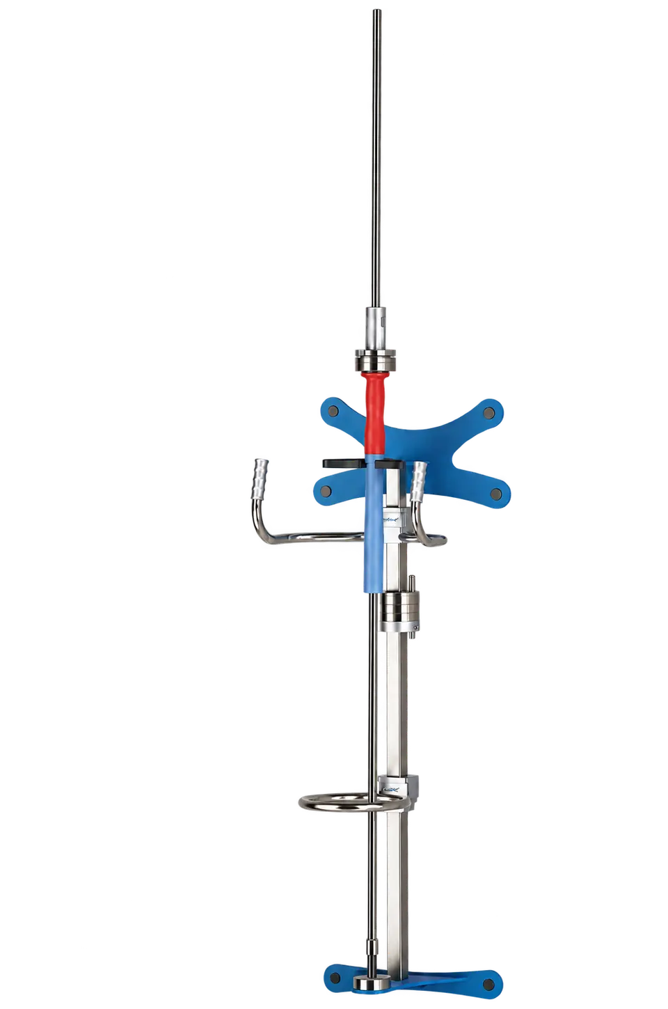
PRO WALL places the complete PlyoDyne movement mechanism on a permanent wall-mounted support structure, without the floor-standing frame used by PRO ONE.
01 — WHY PRO WALL
Compact support structure.
Identical core mechanics.
PRO WALL is designed for professional settings where a permanent training position and wall-mounted installation are preferred. It uses the same movement mechanism, Range Control Ring and selected configuration as PRO ONE, but without the floor-standing frame.
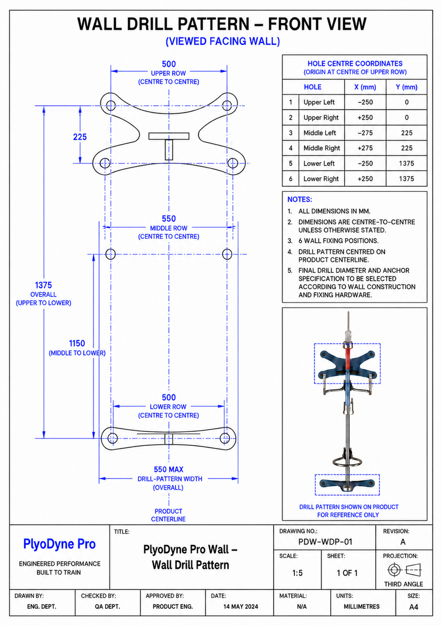
PRO WALL is intended for a suitable load-bearing brick, concrete or equivalent wall. It uses six wall-fixing positions and is supplied with plugs and screws selected for the intended purpose. A competent installer must confirm suitability for the actual wall. Sufficient clear operating space in front of the system remains essential. PRO WALL is not intended for routine relocation.
02 — THE MOVEMENT PRINCIPLE
One straight axis.
Movement in three dimensions.
Shaft tilt
The shaft tilts in multiple directions around the flexible joint.
Shaft rotation
A bearing above the joint allows the complete shaft to rotate.
Keyed handle travel
The handle slides along the groove and rotates only together with the shaft.
03 — ADJUSTABLE SUPPORT POSITION
Set the equipment reference
for the individual task.
Height-adjustable ring
Move the Range Control Ring vertically to leave shaft tilt free, define its maximum range or support the shaft.
Height-adjustable support handles
Move the support-handle assembly up or down to suit the user’s body dimensions, starting position and intended exercise.
Securely locked
After adjustment, the ring and support handles are locked in their selected vertical positions.
The ring affects shaft tilt and support; it does not limit handle travel along the shaft. The support handles provide a separate physical reference for the user. These are equipment settings, not a treatment protocol.
Passive Safety HolderKeeps the training handle securely parked when it is not in use.
04 — S AND M CONFIGURATIONS
The same PRO WALL.
A different training configuration.
S
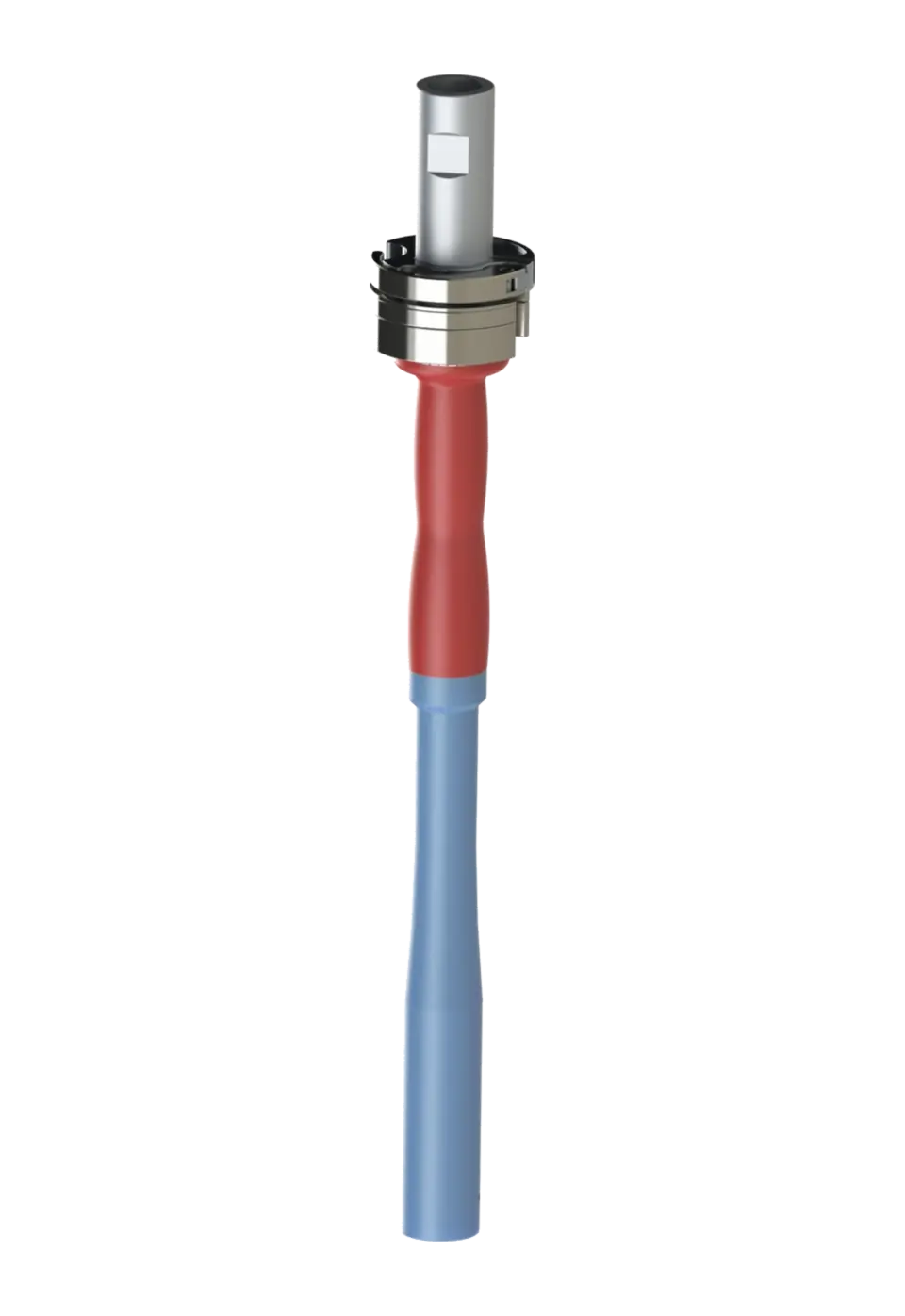
Weighted handle
Includes the standard 2,410 mm exercise shaft, weighted handle and complete weight set: 1 × 25 g · 1 × 50 g · 4 × 100 g · 1 × 0.5 kg · 4 × 1 kg.
M
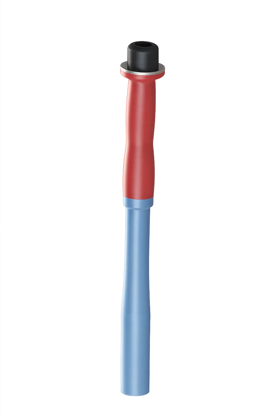
Adds lightweight handle + shaft
Includes everything in S, plus a lightweight handle and a lightweight hollow aluminium exercise shaft (2,410 mm × Ø25 mm · 1.9 kg).
PlyoDyne® PRO WALL
SPACE REQUIREMENT
Compact footprint. Defined exercise area.
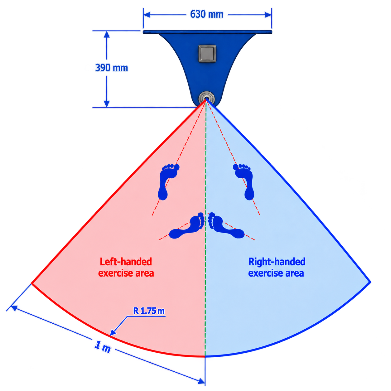
Recommended clear floor space≈ 2.0 × 2.40 m
Minimum ceiling height2.50 m
Exercise radius1.75 m
Wall-mounted width630 mm
Wall to base-plate tip390 mm
Joint centre380 mm from wall
Clear movement space
The illustrated sector represents the clear exercise space required in front of the PRO WALL. Left-handed, right-handed and two-handed exercises are performed within this same operating area. The equipment itself occupies only the much smaller wall-mounted projection area.
Allow additional clearance where necessary.
Consider the user, circulation and surrounding walls, furniture, lighting, fittings or other objects.
Consider the user, circulation and surrounding walls, furniture, lighting, fittings or other objects.
Room-planning note: the approximately 2.0 × 2.40 m recommendation is a practical room-planning allowance around the illustrated exercise area. It is not the physical footprint of the PRO WALL.
TECHNICAL SPECIFICATIONS
Wall-mounted width630 mm
Wall to base-plate tip390 mm
Joint centre380 mm from wall
Exercise radiusR 1.75 m
Clear floor spaceapprox. 2.0 × 2.40 m
Minimum ceiling height2.50 m
Standard shaft length2,410 mm
05 — SAFETY & INSTALLATION
Safety and installation information.
Install only on solid brick, concrete or an equivalent wall confirmed suitable by a competent installer.
Use all six wall-fixing positions. The installer must confirm that the plugs and screws suit the actual wall.
Keep the complete shaft movement path clear, including the area behind the user.
Use indoors under normal room conditions and protect the equipment from moisture, heat and prolonged sunlight.
Use only the supplied or approved weight set up to a total of 4.975 kg.
PRO WALL is not intended for routine relocation. Removal and reinstallation require a competent installer.
YOUR INSTALLATION
Could PRO WALL fit your setting?
Tell us about the wall construction, available operating area and how you intend to use the system.
Discuss your application