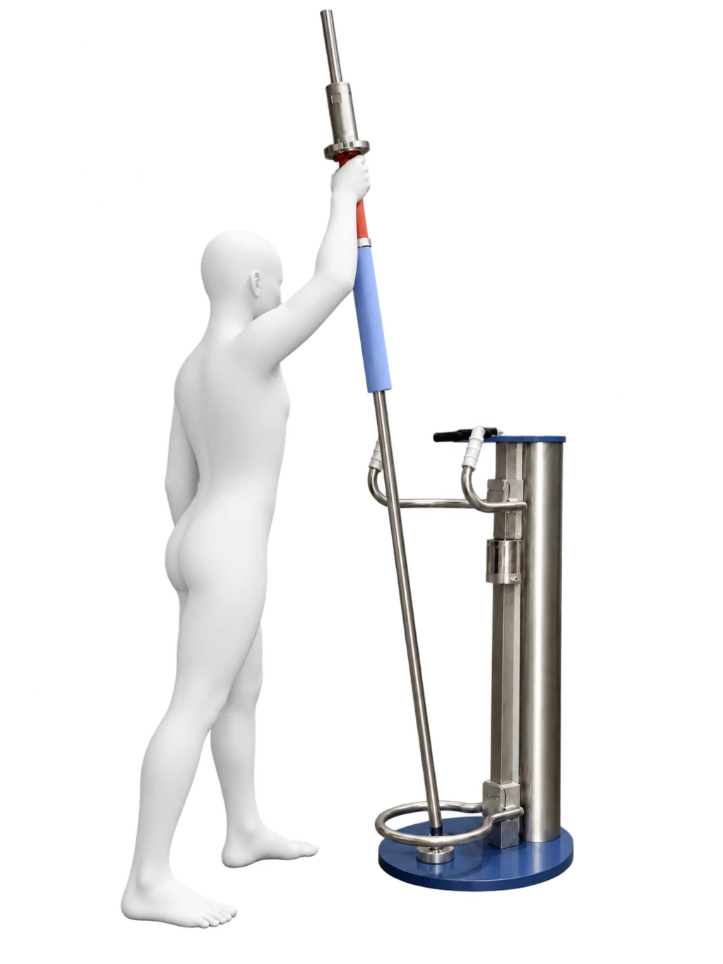
Shaft tilt
The flexible joint allows the straight shaft to tilt in multiple directions.


HOW PLYODYNE® WORKS
PlyoDyne does not guide the body through one pre-programmed path. It provides defined mechanical conditions within which the user creates the movement.
01 — THREE MECHANICAL MOVEMENTS
The flexible joint allows the straight shaft to tilt in multiple directions.
A bearing directly above the flexible joint allows the complete shaft to rotate around its axis.
The handle slides freely along the straight shaft.
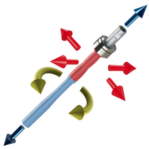
This illustration shows the three movement possibilities combined in one PlyoDyne system.
The available tilt can be left free, limited or supported by adjusting the Range Control Ring.
THE DEFINING RELATIONSHIP
The groove mechanically keys the handle to the shaft. The handle can travel along the shaft, but it cannot rotate independently around it.
When the bearing-mounted shaft rotates, the handle rotates with it as one coupled assembly. The straight 25 mm shaft passes through the centre of the handle; there is no bend or offset in the shaft path.
VISUAL FOCUS
Looking forward towards the equipment provides a stable visual reference. Once the movement is controlled, following the travelling hand with the eyes allows the head and upper body to turn naturally with the movement.
Begin this variation slowly with a low load. Return the gaze forward if balance decreases or dizziness, neck discomfort or loss of movement control occurs.
PASSIVE SAFETY HOLDER
During training, the handle slides freely along the shaft. When it is not in use, it can be moved into the Passive Safety Holder.
The holder keeps the handle securely in its parked position and helps prevent it from sliding down the shaft unintentionally.
To resume training, lift the handle out of the holder and confirm that it can travel freely along the shaft.
Before exercise, check that the handle is fully released from the holder and moves freely.
02 — SHAFT TILT AND SUPPORT
Move the Range Control Ring vertically to leave shaft tilt free, define its maximum range or support the shaft.
Move the support handles up or down to suit the user’s body dimensions, starting position and intended exercise.
Lock the ring and support handles securely after selecting their vertical positions.
The ring controls shaft tilt and support; it does not limit the handle’s travel along the shaft. The support handles provide a separate physical reference for the user.
03 — PRACTICAL ADJUSTMENTS
The video demonstrates how to reposition the Range Control Ring and support handles. The accompanying instructions explain how to add or remove weights from the weighted handle.
Support the component, open its height-adjustment clamp and move the Range Control Ring or support-handle assembly vertically to the required position. Close the clamp fully and confirm that the component is firmly secured before use.
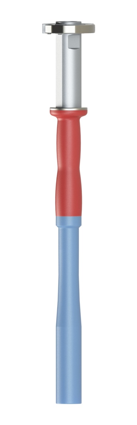

The retaining clamp secures the selected weights on the weighted handle.
Always check that the clamp is fully closed and that all weights are securely retained before training.
04 — INERTIAL RESISTANCE
The mass of the shaft and selected handle resists changes in their motion.
Weights fitted to the S handle increase mass in combinations beginning at 25 g.
Mass and its distribution affect the resistance as the keyed shaft-and-handle assembly rotates around its axis.
These contributions are not three interchangeable “weights”. The mechanical demand also depends on configuration, handle position, direction, speed and acceleration.
PRODUCT BROCHURE
Review the movement principle, adjustable components, S and M configurations, technical specifications and practical delivery information in one printable document.
NEXT STEP